G-Code Controller
Machine control software that combines a graphical part program development, animation and verification into a powerful PC based machine tool controller.
What type of Machine Tool?
Tools enabling you to control motion over a specified path using a dialect of the RS-274 machine tool control language, commonly referred to as "G Codes". Although the graphics support three dimensions of linear control, the product can accommodate up to six simultaneous axes of combined linear and rotary motion, supporting a variety of machine tool applications. This product combines an exceptional conversational interface with the superior speed and smoothness of Indexer LPT/XQ (required).
Features
- 1) Part Programming and Simulation
- 2) Dry Run Cycle
- 3) Offset Compensation
- 4) Optimized Radius Offset
- 5) Three Dimensional Arc Interpolation
- 6) Canned Cycles
- 7) Fixture Offsets
- 8) Multiple Program Capacity
- 9) Unlimited Subroutine Nesting
- 10) Intelligent Start/Stop Spindle and Coolant Control
- 11) User Definable M, T and S codes
- 12) SMOOTH Look-Ahead Contouring
- 13) Menu Driven Setups
- 14) Convenient Controls
- 15) Safety Considerations
- 16) Diagnostics
- 17) NEW FEATURES FOR VERSION 2
Features:
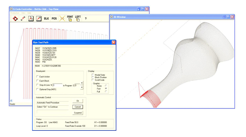
1) Part Programming and Simulation
Whether you generate your part program from other commercially available CAD/CAM systems, or from within this program using Notepad or other text editors - visualizing, simulating and verifying your part program is quick and convenient. The same graphics and controls that are used for simulation are available during production operations.
2) Dry Run Cycle
After virtual simulation you may wish to further verify your part program by means of a Dry Run. Dry Run operation ignores programmed feed rates, operating at the "Dry Run Speed" that you specify for the job. S, T and selected M codes are also disabled during the Dry Run cycle.
3) Offset Compensation
H and D offset tables hold up to one hundred (100) tool lengths and diameters. Tables can be stored and retrieved with the job set-up for machines designed with removable tool trays.
4) Optimized Radius Offset
Radius Offset (Curf Width) compensation selects the best straight line path across vertex (corner) points on outside contours, eliminating tool dwell at the vertex. Look-ahead Z axis plunge determines X-Y radius offset of vertical (Z axis) tool plunge into complex contours - simplifying programming the tool to appropriate X-Y positions for plunging. This feature is especially convenient for repetitive cycles of contours in X-Y-Z that incrementally plunge the tool along the Z axis before each cycle.
5) Three Dimensional Arc Interpolation
Arc interpolation in any of three selected planes is incorporated into a smoothly traversed contour (look-ahead into arcs).
6) Canned Cycles
Canned programming cycles G80-G87 simplify programming for a variety of machining operations: drilling, tapping, spot facing etc. that include repetitive cycling, programmable dwell, spindle control and/or pause for operator interaction.
7) Fixture Offsets
Up to six fixture offsets can be used per job. Interactive manual motion controls allows you to set up fixture offset values using the motion controlled tool as a guide - a great set-up convenience.
8) Multiple Program Capacity
Up to ten programs can be easily assigned to each job. Program file names are associated with part program "O" word references by means of an easily accessible menu. From the same menu you can "snap" your part program into Notepad or your favorite text editor or word processor."Save" and "Reload" to see your part program develop graphically as you write it. Part program development has never been easier!
9) Unlimited Subroutine Nesting
Call a subroutine from within a subroutine, and within that subroutine call another subroutine - as many times as you would like.
10) Intelligent Start/Stop Spindle and Coolant Control
Spindle and coolant controls appropriately turn off and on in response to program Stop's and Resume's.
11) User Definable M, T and S Codes
Up to one hundred M and T codes can be customized using lists of Indexer LPT commands, which are easily maintained by means of the built in list editor. S codes can also be customized with Indexer LPT scripts. Macro capability provides for intelligent stage positioning and return from previous position, "wait on switch input", and digital output. These features can be used to accommodate external PLC's, tool changers and retrofit of diverse types of equipment, including punch presses.
12) SMOOTH Look-Ahead Contouring
Intelligent "N block" look-ahead takes full advantage of Indexer LPT/XQ's massive look-ahead contouring capacity. Not simply a deceleration over-ride,look-ahead modulates acceleration to maintain as close to cutting speed (vector rate) as possible without over-stressing the stages on anticipated changes in direction. Look-ahead technology does not limit the number of interpolations it needs to read ahead to anticipate deceleration.
Look-ahead technology allows you to automatically arrange for all calculation dwell to occur at the times that the tool is not in contact with the work. You can even change feed rates and execute M commands after initial tool entry into the work and NOT HAVE calculation dwell at the point after the initial entry and before the complex contour. This is useful in milling machines and routers, but especially important for laser and plasma cutting machines where post-entry dwell must be precisely controlled.
13) Menu Driven Setups
Setup menus are easy to use and intuitive. There are two types of set-ups: one accommodates the design of your machine, and the other accommodates the job at hand. Machine design set-ups include such things as the customizing of M, T and S codes, association of the stages of motion with Indexer LPT axes, and the set up of controls for start, feed hold and joystick jog. Once made, these set-up values are rarely changed.
Job set-ups include things that are more closely connected with the particular part that is being made, and include such things as the the name of the H & D offset file, arc accuracy, fixture offset positions, and a number of "default" values, as well as the file names for the part program(s). Job set-ups are easily duplicated, modified, saved to and retrieved from disk. Typically only a few things will change from job to job, such as the name of a part program file. You may wish to save frequently used set-ups as templates for different types of jobs - or you may wish to save set-ups for complete jobs that you can retrieve by name and run at a later time.
14) Convenient Controls
Menus for automatic limit switch seek and Machine Home location make it easy to start up and initialize the machine at the beginning of the work day. Optional Indexer LPT lists are executed within the limit seek sequence to initialize special machine features (such as a sequence to "square up" dual X stages on a type of gantry machine that uses dual X drives).
3D and Ortho Graphics reflect the part program with respect to the limit switch boundaries. If you relocate Machine Home or Fixture Home locations the graphics will reflect the changes.
Joystick and Manual Positioning menus allow easy stage manipulation for job set-up or for motion after a program Stop that requires operator intervention.
Feed Hold control allows for an immediate, decelerated and controlled program Stop. You can also set stop points and optional stop points within your part program, or use the operator panel to set a stop point at a particular program and block number.
The operator panel allows you to enable a variety of graphical and display options during dry run and production run cycles. It provides you with useful prompts and information during the cycle, and allows quick and easy access to the manual controls during a program Stop.
A menu we call "Instant Block" allows you to type in and execute machine commands during a program Stop.
15) Safety Considerations
User definable cycle Start specifies either the keyboard or one or two external start switches or relays. If it is from the keyboard, TWO keys are required to effect a cycle Start or Resume. You cannot effect a cycle Start by means of a mouse click, or by means of a single keyboard keystroke.
For designs where it is prudent for the operator to account for the position of both of his hands, set-ups provide for two start switches. The software checks that both switches are open before acknowledging that both switches are closed - in an attempt to defeat the all too common practice among some production workers of tying one start switch closed.
(For designs that need to accommodate external control relay control, such as may be necessary for a PLC controlled automatic loader/unloader, cycle Resume can be set up to be accomplished by means of relay contacts with no keyboard or mouse intervention).
Once the part program begins execution, the G Code Controller will force itself into the Windows foreground and not allow other programs to run on top. Interaction with other programs is allowed during part program development, but when the part program is in control over the machine tool, information regarding the operation of the machine is displayed in front, and other programs that may have open windows are forced into the background.
16) Diagnostics
Diagnostic screens assist you not only in testing the design of your machine, but also in troubleshooting for field repair. The easily accessible diagnostic screens are continuously updated to show the "live" status of cycle start, joystick jog, feed hold and limit switches.
Another diagnostic screen shows a list of either system errors or errors that occur when interpreting a part program. This tool is particularly useful in part program development.
back to top