HPGL Controller: Design your own computer controlled machine tool! and use familiar CAD/CAM tools, such as AutoCAD, DesignCAD, Corel Draw, alongside the HPGL Controller's own graphical editor.
|
Graphically control these types of machines:
|
click over images to enlarge
Description
- 1) The Physical Stages
- 2) The Motor Controls
- 3) Putting it All Together
- 4) Making a Part
- 5) Easy Set-Ups
Features
- 1) Graphical Tool-Path Editing
- 2) Nesting
- 3) Extensive Smooth Look-Ahead Contouring
- 4) Immediate Feed-Hold
- 5) Break a Tool? Backup and Retrace
- 6) Radius Offset Compensation
- 7) Convenient User Interface
- 8) Variable Depth Plunge
- 9) Incremental Plunge
- 10) Step and Repeat
- 11) Scaling
- 12) Multiple Heads
- 13) Auxiliary Commands
- 14) Tool Path Preview
Description
1) The Physical Stages
The hardware elements consist of at least two motor controlled stages which effect motion at right angles (the X and Y axes) similar to a plotter. A third axis (Z axis) can either be motor or solenoid controlled. Stages convert the rotation of the step motor into linear motion by means of lead screws, belts, or cable. Some designs use stages to move a tool across the work. Other designs manipulate the work under a stationary tool.
2) The Motor Controls
Control elements include an IBM compatible computer, Indexer LPT device driver software, step motor drives (amplifiers), and step motors. Some types of systems use step/direction controlled servo amplifiers. All signal inputs and outputs are accessed through Indexer LPT. Indexer LPT software converts your computer into a sophisticated motion controller, generating the control timing signals and monitoring inputs directly over an industry standard parallel (printer) port. Since Indexer LPT is a "background" program, and is accessed similar to a disk file, it can be used with a broad base of software available from different companies, not just our HPGL Controller. We remain committed to this "open architecture" approach to machine design.
3) Putting it All Together
A collection of set-up menus and dialog boxes lets you customize the HPGL Controller to your particular design. For example, you specify what units you are working with (inches, cm, etc.), how many motor steps occur per unit of travel, and the travel distance of each stage. If your Z axis is solenoid controlled, you specify which Indexer LPT command is used to activate the solenoid, and optional inputs to monitor to assure the action is complete. You also specify rapid traverse rates, and what types of manual controls (start switches, feed hold, joystick jog etc. ) you wish to incorporate. You can even build multiple Z stages into your design. A diagnostic menu assists you by showing a live presentation of the status of the limit and control switches. Set-ups unique to the design of the machine are saved in a .INI file located in the WINDOWS directory, which is automatically read each time the program is run. You may restrict access to these set-ups with a password to avoid accidental changes. Once you finish customizing the system set-ups, your machine is ready to run.
4) Making a Part
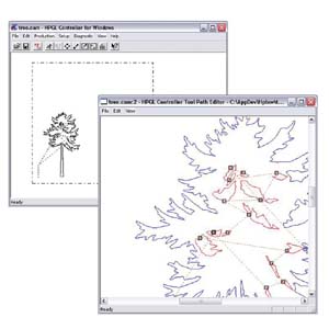
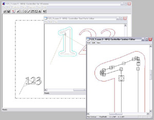
Lines drawn from your favorite CAD program define the path of the tool. After drawing your tool path, you output ("plot", or "print") to an HPGL type file. Most CAD programs have this capability, and will prompt you for the name of the file before it is saved to disk. Now switch tasks to the HPGL Controller. In the "Tool Path" dialog box you select the HPGL file you just created. A menu pick converts the information in the HPGL file into an Indexer LPT script which can be used to run the tool. If you wish, you can graphically edit the path, arrange tool path direction and order and specify tool radius offsets.
From the main display window the tool path is shown in solid lines, rapid traversals (tool-up motion) are shown in dotted lines, and limit switch boundaries are shown in dashed lines. Using convenient menu picks, you manually adjust the tool carriage to the correct starting position. Snap on the "Run" icon, press the Start switch, and automatic operation is on its way!
5) Easy Set-Ups
Just as there is a collection of set-ups which define the design of your machine, there is another collection of set-ups which are unique to the part which you are making. Part specific parameters comprise what we call the "CAM" set-up. The CAM set-ups are easily changed, duplicated, and saved under a user defined name. CAM set-ups include tool speeds, plunge depths, scale factor, and other features which you will find useful and flexible.
Features
1) Graphical Tool-Path Editing
The new Tool Path Editor makes developing tool paths easier than ever. For simple shapes there is no need for another CAD package. Simply draw your tool path and/or drilling plunges using the built in Contour Editor. For more complex paths, import paths from your CAD software's plotter output - then use the Tool Path Editor to snap in tool path direction and ordering - all from a rapid, intuitive, Windows based graphical display.
2) Nesting
Nesting optimizes material usage. Individual contour shapes are easily saved to disk for convenient retrieval and placement into nested jobs. Retrieval, rotation and placement are intuitive, visual, rapid and and accurate. Try this out for speed and convenience: Nest the shapes you need into a pattern that "fits" into its corresponding sides (tessellates). Then use the "Step and Repeat" menu to define rows and columns of parts. Preview the entire pattern - Run the job!
3) Extensive Smooth Look-Ahead Contouring
Takes full advantage of the extensive look-ahead capability of Indexer LPT/XQ. Extremely extensive and complex shapes are traversed in a continuous, acceleration modulated motion. This not only results in a better quality cut, but also can substantially increases production throughput.
4) Immediate Feed-Hold
Bring the tool to an immediate decelerated pause anywhere within the job - even in the middle of a contour. Optionally retract the tool and locate it anywhere for tool replacement or maintenance. The HPGL Controller will remember where the tool was retracted, and position it in the proper position when the job is resumed.
5) Break a Tool? Backup and Retrace
This new feature allows you to recover from a Feed-Hold-Retract condition where the tool path must be retraced. Menu options allow you to back up segment by segment, or to back up all the way to the location of the tool plunge into the contour.
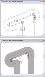
6) Radius Offset Compensation
Draw the contour path that you desire to trace, then with a simple snap determine whether the tool should "Offset Left" or "Offset Right" to make the edge of the tool conform to the contour. Up to ten different tool diameters can be specified per storable/retrievable job setup. Optimum paths are automatically generated for inside and outside angles. View options allow you to preview the centerline of the actual tool path, or the entire path width. Tool path and radius errors are easily detected and corrected.
7) Convenient User Interface
Positioning for job set-up is a breeze with intuitive controls.
8) Variable Depth Plunge
Tool cutting speeds, plunge speeds, and depth of Z axis plunge are assigned to HPGL pen numbers (colors).
9) Incremental Plunge
This option lets you automatically repeat a tool path, incrementally plunging the Z axis deeper and deeper with each pass - excellent for removing large amounts of material.
10) Step and Repeat
Use this feature for manufacturing multiple parts in rows and columns. Easy set-ups lets you designate number of rows and columns and distances between parts. You may also start and stop on any part in the matrix pattern.
11) Scaling
Scale your tool path up or down by virtually any scale factor - odd ratios do not result in accumulated round off error.
12) Multiple Heads
Support for up to four Z axis stages. Automatically compensates for X-Y offset position of the heads. Assign heads to HPGL pen numbers (colors).
13) Auxiliary Commands
Automatically execute lists of Indexer LPT commands which activate special features you design into your machine. Lists are executed before and after tool path, Z axis plunge, and head change.
14) Tool Path Preview
View your tool path before starting. This feature is especially convenient when setting up for step and repeat operations. A "Carriage Preview", helpful in avoiding limit boundaries, views the tool carriage motion including X-Y offsets for multiple heads.